Autonomous heating systems can be built in many ways. One of the most popular types of home heating system is the liquid heat transfer system. Usually it is used as water with special additives.
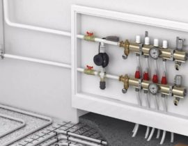
Heating distribution manifold
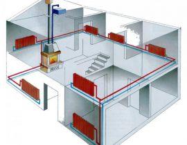
Such a system may have several heating circuits, for example, heating through radiators and through underfloor heating. In order for the water in such a system to be distributed evenly, a distribution heating collector is needed.
Content
Purpose of the heating manifold
The absence of a distribution manifold in a water heating system can lead to the fact that water can flow unevenly into different circuits of the system. As a result, you will have a hot floor and cold radiators, or vice versa.
This may be due to the fact that several circuits of the heating system can be connected to one boiler outlet. The liquid flows through such connections unevenly, as a result of which part of the premises will not have enough heat. But it is precisely on the amount of coolant passing through the pipes, the volume and speed of its movement that the efficiency of the heat supply system depends.
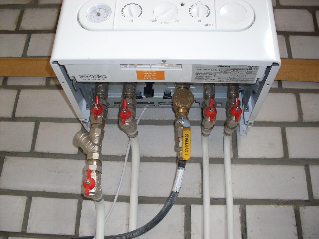
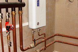
pipes from the boiler
Some home owners try to solve this problem by installing additional pumps and control valves. But this only complicates the system and does not always lead to a uniform distribution of the coolant.
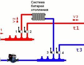
How is the coolant distributed in a private house?
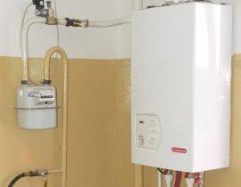
Take, for example, a heating system for a private house with an area of 100 square meters. The device for heating water will be a wall-mounted gas boiler with one outlet pipe with a diameter of ¾ inches.
In the house we have two heating circuits and one circuit that heats domestic water with indirect heating. All circuits are built from pipes with a diameter of 1 inch. How to calculate and build an efficient heat supply system?
First of all, we clarify for ourselves that the main reason for poor-quality heat supply is an elementary lack of coolant in the system. But the main reason for this shortage is excessively narrow distribution pipelines.
Thus, to increase the efficiency of the thermal system, that is, to increase the diameter of the distribution pipes, there are two ways:
heat flow distribution
- When using boilers with built-in pumps, a hydraulic arrow (flow distributor) is connected to them. In this case, each heat consumption circuit must have its own circulation pump. But such a device will only work in a small building. With an increase in heated areas, its efficiency and reliability drops sharply.
- The most reliable way would be to connect a water distribution manifold to a heat source.
The most perfect type of distribution manifold is called camplanar. With its help, the problem of connecting pipes of different diameters and volumes of the placed coolant is effectively solved.
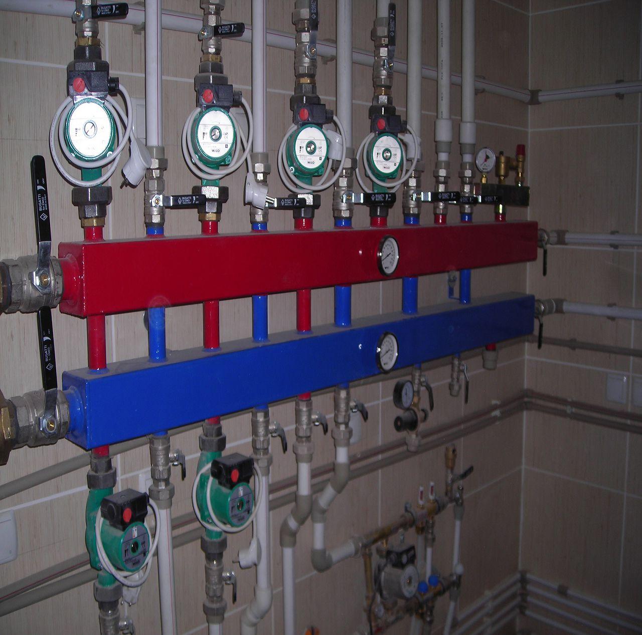
distribution hydrocollector for 4 circuits
Consider how to create heat distribution systems with your own hands.
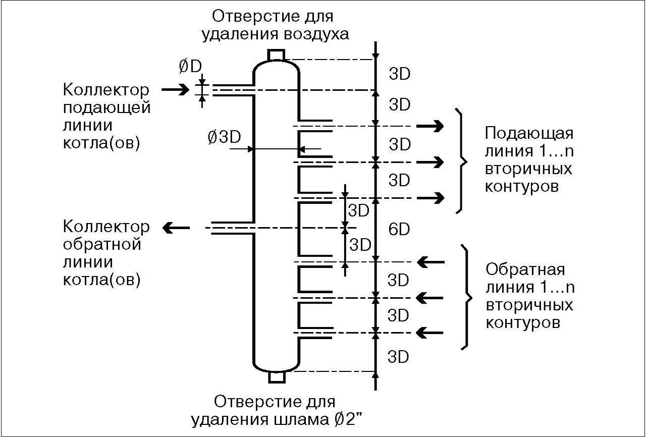
Hydraulic arrow and its function
This is a fairly simple device. It can be made from a piece of pipe with a cross section three times larger than the boiler outlet. On the ends of the segment, it is necessary to weld plugs of a curved shape. Threaded holes are then cut into the plugs. They will serve to release air or drain water. We drill holes in the body of the pipe, in which we also cut the thread. We will connect the boiler outlet and heating circuits to them. Frame hydroguns after that it is necessary to sand and paint.
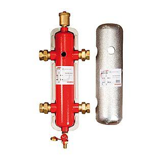
hydro gun
Compalan distribution manifold
Despite the fact that there is a large assortment of distribution manifolds of different sizes in hardware stores, it is sometimes difficult to choose a device exactly for your heating system. Either the number of contours or their cross section may not match. As a result, you will have to make a monster from several collectors, which will obviously not have the best effect on the efficiency of the heating system. Yes, and such pleasure will not be cheap.
At the same time, you should not believe the stories of the "experienced" that the system can work fine even with a direct connection to the boiler. This is mistake. If your heating system has more than three circuits, then installing a distribution manifold is not a whim, but a necessity.
But if there is no distribution manifold on sale that suits your parameters, it is quite possible to do it yourself.
Making a distribution manifold with your own hands
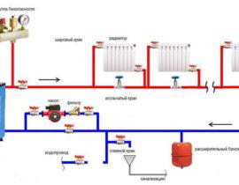
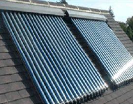
The distribution manifold project is developed based on the number of heating circuits in your system.Estimate where your heating boiler is located, which inlet and outlet pipes it has, how many heating circuits or indirect heating circuits will be involved in the heating system. Perhaps you are planning to increase the number of circuits in your house, for example, add another room next year. Solar collectors, a heat pump and other devices can also be connected to the distribution system. We also consider all distribution heat systems, including underfloor heating, heating radiators, fan coil units and so on.
We draw up a diagram of our heating system, given that each circuit has a hot water supply pipe and a return pipe.
When designing the system, be sure to determine the location of additional equipment, such as the expansion tank, automatic make-up valve, drain and fill valve, thermostat group, and so on.
Performs spatial design, that is, we determine from where and where pipes will be connected to our distribution manifold. Practice suggests that nozzles are usually mounted on the ends of the collector for connecting a solid fuel boiler and for indirect heating. If you have a wall-mounted gas or electric boiler in your system, it cuts from above or also into the end.
Based on the available information, we draw up a drawing of the future distribution manifold. It is convenient to use graph paper for this. The distance between the nozzles should not be less than 10 centimeters, but they should also not be spread wider than 20 centimeters. For one heating circuit, the distance between the supply pipe and the return pipe should not be less than 10 centimeters.It is desirable that groups of branch pipes of the same circuit are visually distinguished.
Manifold design
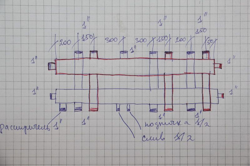
The figure below shows an example of designing a distribution manifold into which six circuits of the heating system will be connected.
At the first stage, we draw two rectangles. This is actually the supply manifold and the return manifold.
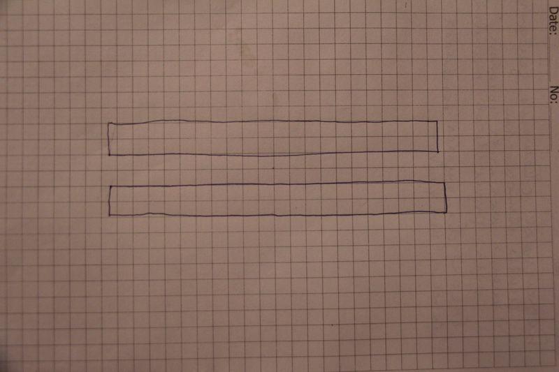
supply manifold and return manifold
We design the connection of a boiler and an indirect heating boiler on the collector ends. Do not forget to put down the cross-sectional parameters of future pipes on the drawing.
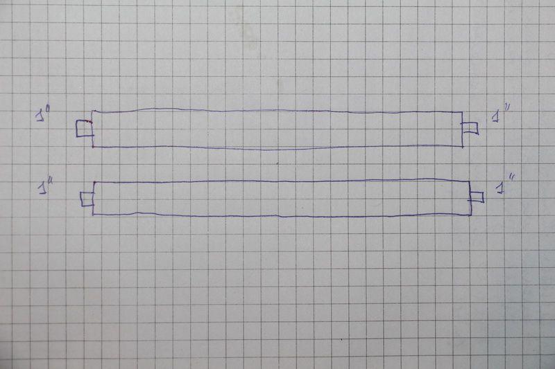
connection of the boiler and indirect heating boiler
We design the connection of heating circuits and additional heating boilers. Do not forget to put down the cross section of the pipes and the dimensions of the nozzles. We sign all designed pipes.
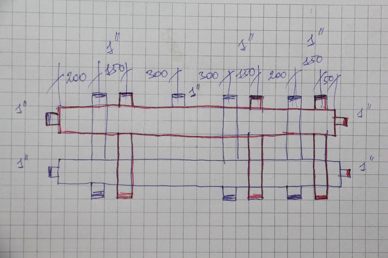
connection of heating circuits and additional heating boilers
At the next stage, we design the connection of additional equipment. In our case, this is an expansion tank, a drain valve, a protective block, a system thermometer. Please note that the coolant supply circuits are highlighted in red, and the return circuits in blue.
connection of additional equipment
It was a rough drawing. We check its correctness and transfer it to the finish on a new sheet of paper. It is on the basis of this project that we will create our own distribution manifold.
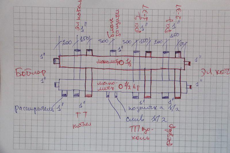
final drawing
We make a distribution manifold
We carry out the calculation of the material required for the manufacture of the collector. The easiest way to do this is in Excel spreadsheets. At the same time, in this program, you can also calculate the cost of materials required for the manufacture of the device. We acquire the necessary source material and prepare tools for self-production.
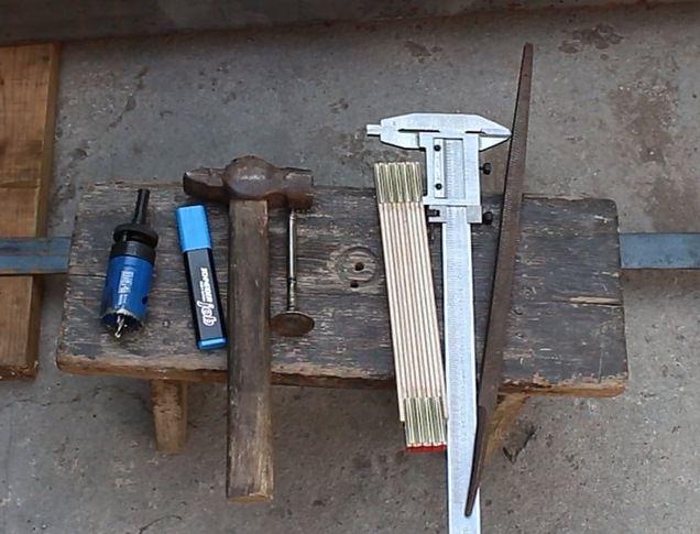
preparing tools
The starting materials for the main parts of the collector will be ordinary or square pipes. We make the necessary markings on them using a caliper, a ruler and a core.
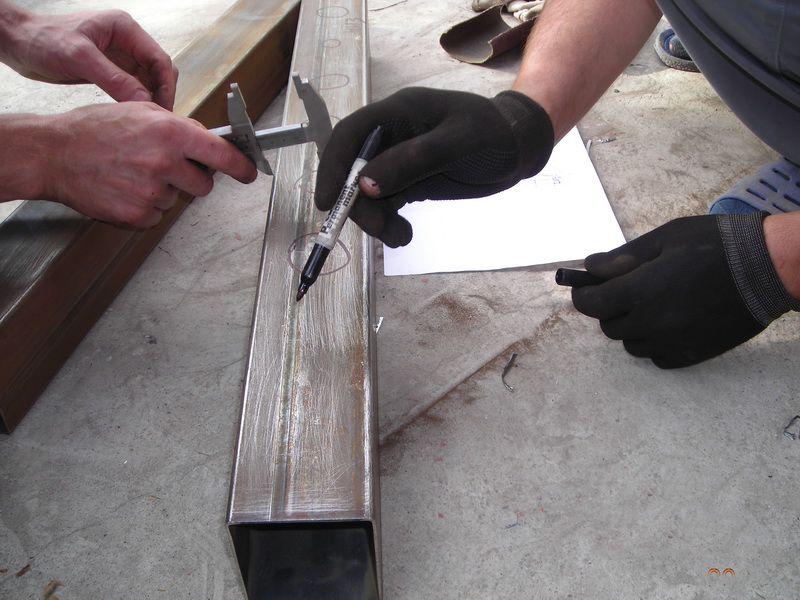
We make the necessary markup
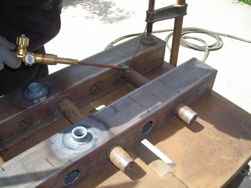
Using a gas cutter, we make holes for the pipes.
making holes for pipes
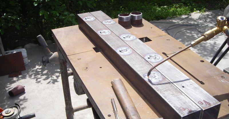
We insert the branch pipes (pieces of pipes with threads) into the seats.
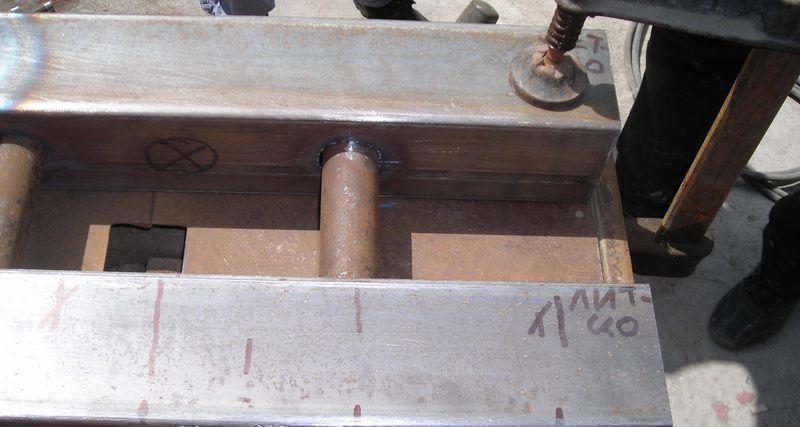
We insert pipes
We fix the pipes by welding. First, rough, and then scald around the entire perimeter.
We fix the pipes by welding
We also weld brackets to the body for wall mounting.
weld brackets to body
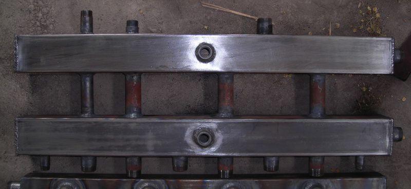
We clean the places of welding from scale and rust.
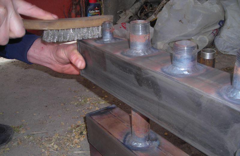
Cleaning up welds
We treat the entire structure with a degreasing agent, cover it with paint and varnish.
treated with a degreasing agent, coated with paint and varnish
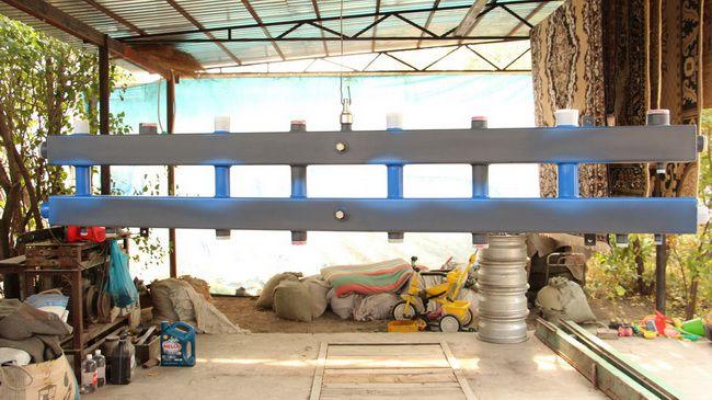
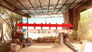
The paint completely sets in two or three days and we have at our disposal a self-made distribution manifold. Now it remains only to install it in place and connect all incoming and outgoing circuits to it.
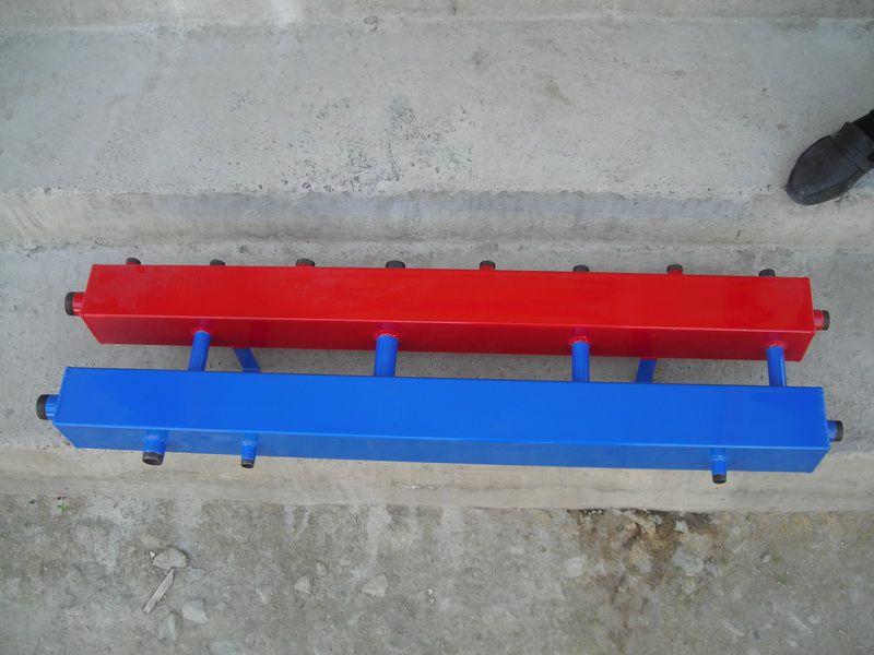
finished homemade distribution manifold
A system with a distribution manifold will work much more efficiently than a simple pile of heating pipes.
In order to catch all the nuances of self-manufacturing a distribution manifold and its scope, we recommend that you watch the training video.
Overview of a homemade distribution manifold